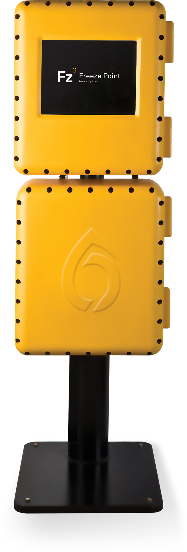
Icon Freeze Point Analyzer

Cutting-edge technology to benefit your process, pocket, and environment.
Product Overview
Innovation that is Rocket Science
46,000 flights every day are ensured safe because the jet fuel is analyzed by instruments produced by PAC. Icon’s freeze point technology is trusted in airport terminals, as a final step before delivering fuel directly to the aircraft.
The Icon Freeze Point analyzer is our most versatile cold-flow property analyzer, allowing the measurement not only of the Freeze Point but also low-temperature Cloud Point and Pour Point measurements. It can rapidly cool a sample to -100°C without an external chiller system, or even chilled water. The advanced cryo-cooling technology that allows this is the same technology, with the same zero-maintenance design, as used for space exploration.
Icon’s Freeze Point analyzer is a win for the refinery’s process, their pocket, and the environment – with on-line measurement reducing the need for additives and helping to optimize operating conditions. The analyzer is easily optimized for SAF measurements, and other new fuels, enabling the green energy transition.
Key Features
Best cooling performance
Excellent repeatability
Reduced thermal losses
Long-life, zero maintenance
Specs
Inlet Temperature
At least 30°C (54°F) above the highest expected measurement point. Maximum 50°C (122°F)
Inlet Pressure
Maximum 5 bar (72.5 psi)
Outlet Pressure
Can be returned to pressure, provided minimum flow requirement is achieved. Typically requires a minimum 1-bar differential across the analyzer.
Sample Flow (continuous)
Minimum 12 L/H
Recommended 18 L/H
Sample Quality
Filtered to 10 microns (μm). Sample should be ‘clear and bright’ at room temperature and contain no free water.
Instrument Air
Required
Pressure
0.2 bar (3 psi) for cell enclosure cooling (included) and optional electronics enclosure cooling.
Consumption
Typically 5-10 L/H
Quality
ISO 8573.1 Class 3
ANSI / ISA-7.0.0
Coolant
Potable water or antifreeze mixture.
(Do not use sea water)
Inlet Temperature
Minimum 10°C (50°F)
Maximum 45°C (113°F)
Inlet Pressure
Maximum 10 bar (145 psi)
Outlet Pressure
Can be returned to pressure, provided minimum flow requirement is achieved.
Flow Rate
Minimum 20 L/H
Recommended 25 L/H
Filtration
100 microns (μm)
Viscosity
Maximum 10 cSt
Breather
Must be to atmospheric pressure.
Power
115-230VAC 50-60Hz, Max 500VA
Location
Unit must be located out of direct wind sun and rain.
Ambient Temperature
+5 to +40 °C
Ambient Humidity
0-95% RH, non-condensing.
Control System
Based on fan-less industrial PC with solid state hard drive.
Graphical User Interface (GUI)
17” armored glass touchscreen. The GUI is used to program the unit and display current and historical analyzer results and alarm status.
Language
User-selectable multilingual display.
Hazardous Area Certification
Exd certified to ATEX, IECEx, UKEx, TIIS, and EACEx standards, suitable for zone 1 or zone 2 use in gas groups IIA, IIB, or IIB+H2, with a variable T-rating depending upon application. It is also ETL listed for the USA and Canada Class 1, Div 1, groups B,C,D.
IP Ratings
Tested and certified to IP66/IP67 (dust tight and protected from temporary total immersion in water).
Measuring Range
Adjustable down to -100°C (-148°F)
Repeatability
Equal to or better than repeatability criteria of the relevant test method.
Cycle Time
Typically, 5-10 minutes.
Analog Outputs
2 x 4-20mA (active) isolated outputs provided as standard for:
Freeze point or cloud point result (analysis mode dependant), and optionally also pour point result.
Digital (Contact) Inputs
Run / Standby: reads a customer supplied latching switch to toggle between run and standby modes.
Remote Cal: reads a customer supplied momentary switch to remotely initiate a calibration cycle.
Remote Val: reads a customer supplied momentary switch to remotely initiate a validation cycle.
General Fault Alarms
Alarm limits can be configured for monitored conditions, and set to be Fatal, Warning, or Inactive. Active alarms are notified on screen and stored in the alarm history table.
Digital (Contact) Outputs
Fatal Alarm (NC): a general fault alarm that causes the analyzer to suspend its operation when triggered.
Warning Alarm (NC): a general fault alarm for notification only.
New Result (NO): a variable-length momentary contact to notify that a new analyzer result is available.
Data Valid (NO): indicates that the analyzer is currently running on a process stream, and that data is valid. As opposed to when in standby, or when in Cal. or Val. modes.
Cal/Val (NO): indicates that the analyzer is currently in Cal/Val mode.
Spill Alarm (NC): an alarm contact that triggers if a leak is detected in the analyzer enclosure.
All contact ratings are 24VDC 0.5A, 230VAC 1A.
Digital (Signal) Outputs
Calibration Valve: provides a 24VDC signal to an external solenoid valve to switch between process and calibration samples.
Analog Inputs
Set of 4x inputs (optional)
The analyzer can optionally read up to four 0-10V or 4-20mA active signals. These input values can each have high/low alarm levels associated with them to trigger either of the analyzer’s general fault alarms.
Digital (Contact) Inputs Set of 4x inputs (optional)
The analyzer can optionally monitor up to four volt-free external contacts or customer alarms. These contacts may also be included in the analyzer alarm table to trigger the general fault alarms.
Communications
Modbus RTU or OPC over RS485 or Ethernet (TCP/IP), with optional fiber optics. Optional OPC server software.
Documentation
| Title | Description | |
| Brochure | Freeze Point Analyzer Brochure | Download |
Related Resources

PAC Overview Brochure
Discover PAC’s comprehensive portfolio of solutions designed to elevate your laboratory operations, streamline process workflows, and deliver powerful digital insights. Download the full overview now...
Read More
Guide: Sustainable Fuels Outlook
PAC’s Sustainable Fuels Outlook provides an in-depth analysis of the current energy industry, where regional differences in the pace of transition and global uncertainty shape...
Read MoreTransforming the Industry with PACe Digital Ecosystem
Transforming the Industry with PACe Digital Ecosystem.
Read More